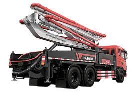
A concrete arm pump is a widely used concrete conveying equipment in construction engineering, which has the advantages of large conveying capacity, long conveying distance, and high conveying height. The arm pump mainly consists of a pumping system, hydraulic system, lubrication system, etc., among which the hydraulic system is a key part of achieving concrete pumping.
Application Scenarios Of Boom Pump
Arm pumps are widely used in various construction projects, such as concrete pouring in high-rise buildings, construction of large-span bridges, and construction of highways. Its powerful conveying capacity and high flexibility make boom pumps essential for modern construction.
1. Features of boom pump
- Large conveying capacity: The arm pump has a large conveying capacity and can meet the needs of large-scale concrete construction.
- Long delivery distance: The arm pump can transport concrete to distant construction sites with a reasonable pipeline layout.
- High conveying height: The conveying height of the boom pump is relatively high, which can transport concrete to higher floors or bridge sections.
- Easy to operate: The operation of the boom pump is simple and easy to understand, making it convenient for construction personnel to operate and maintain
- High reliability: The hydraulic system of the boom pump adopts advanced technology and materials, ensuring the stability and reliability of the equipment.
2. The Important Role of Arm Pump Hydraulic System
The hydraulic system plays a crucial role in the boom pump, and its main functions include:
- Power supply: The hydraulic system provides power for the transportation of concrete through the transmission of oil pressure.
- Control arm movement: The hydraulic system controls the lifting, rotation, and expansion of the arm, achieving long-distance transportation of concrete.
- Adjusting flow and pressure: The hydraulic system can adjust the flow and pressure of concrete in the pipeline, ensuring the stability and reliability of the conveying process.
- Protective equipment: Components such as relief valves in hydraulic systems can protect the equipment from overload damage and extend its service life.
3. Working Principle Of Hydraulic System For Boom Pump
The working regulation of the boom pump hydraulic system mainly involves the transmission and control of pressure and flow. The specific process is as follows:
- Oil suction and output: When the hydraulic pump is running, the oil is sucked into the oil tank, filtered through an oil filter, and then enters the hydraulic pump. After the hydraulic pump increases the pressure of the oil, it is transported through pipelines to various actuating components, such as oil cylinders and motors. The oil cylinder drives the concrete through the pipeline under the oil’s action, while the motor drives various working mechanisms to move.
- Control of flow and pressure: In hydraulic systems, the flow rate of oil entering the actuator can be controlled by adjusting the throttle valve or speed regulating valve, thereby controlling the conveying speed and flow rate of concrete. At the same time, safety valves such as relief valves can be opened when the system pressure is too high, releasing excessive pressure and protecting the system from overload damage.
- Oil return and cooling: The oil that completes the conveying task returns to the oil tank from the actuator, and is cooled by the cooler before entering the hydraulic pump for circulation. At the same time, the oil in the tank can be filtered and purified before reuse, improving the system’s economy and environmental friendliness.
4. The Composition And Function Of The Hydraulic System Of The Boom Pump
The hydraulic system of the boom pump mainly consists of a hydraulic pump, oil tank, oil filter, cooler, overflow valve, throttle valve, speed control valve, oil cylinder, and motor. These components work together to achieve stable transportation of concrete and control of various actions. Among them, the hydraulic pump is the power source of the system, providing oil pressure and flow rate; The fuel tank is used to store oil; The oil filter is used to filter impurities in the oil; The cooler is used to cool the oil; Relief valves and other safety valve components are used to protect the system from overload damage; Throttling valves and speed regulating valves are used to regulate flow and pressure; Oil cylinders and motors are used to perform various actions.
